Your first part: a plate with four holes
You will make a 100 × 80 mm plate with a hole in each corner area, 5 mm thick, and change it afterwards by editing a number. You need no CAD experience. It takes about 15 minutes.
The idea behind Extrudo is that you name your numbers. The plate's width, depth and thickness are parameters. You draw once, tell the drawing which parameters it follows, and then change the parameters whenever you like.
Open the app at https://app.extrudo.org.
1. Start a design and add your numbers
On the home screen press New design. Press the name at the top, type
First part and press Enter. Then open the Home tab and press
Parameters.
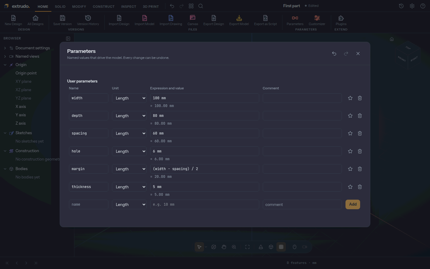
In the row at the bottom type a name, leave the unit on Length, type an expression and press Add. Add these six:
| Name | Expression |
|---|---|
width |
100 mm |
depth |
80 mm |
spacing |
60 mm |
hole |
6 mm |
margin |
(width - spacing) / 2 |
thickness |
5 mm |
margin is worked out from the others: under its row you see = 20.00 mm. It
is the space between the plate's edge and the first hole, so the holes stay
centred whatever the width. Press Esc to close the dialog.
2. Start a sketch on the floor
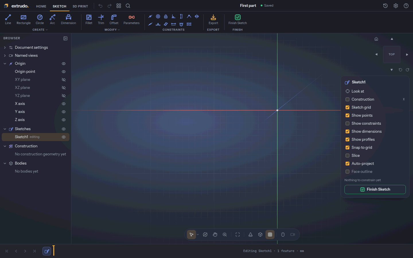
A solid starts as a flat drawing, a sketch. Open the Solid tab, press Create Sketch and choose the XY plane, the floor of the model. The view turns to look straight down on it.
Scroll to zoom out a little so the whole plate will fit. In the Sketch palette on the right, switch Show constraints off: the little symbols are useful later, but they would crowd this tutorial.
3. Draw the plate
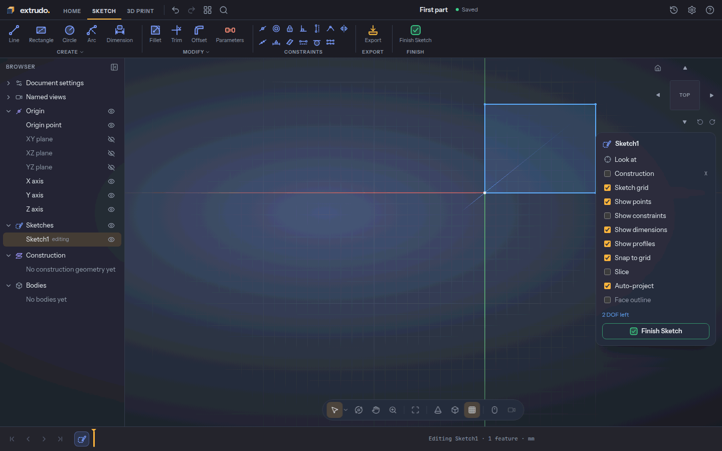
Press Rectangle (or R). Click the origin, where the green and red lines
cross, then click the opposite corner at 100 mm across and 80 mm up. The grid
snaps your clicks to 10 mm steps, so this is easy to hit. Press Esc to finish
the rectangle.
The corner you started on is pinned to the origin. The palette says how many DOF (degrees of freedom) are left: how many ways the drawing can still move.
4. Draw four holes
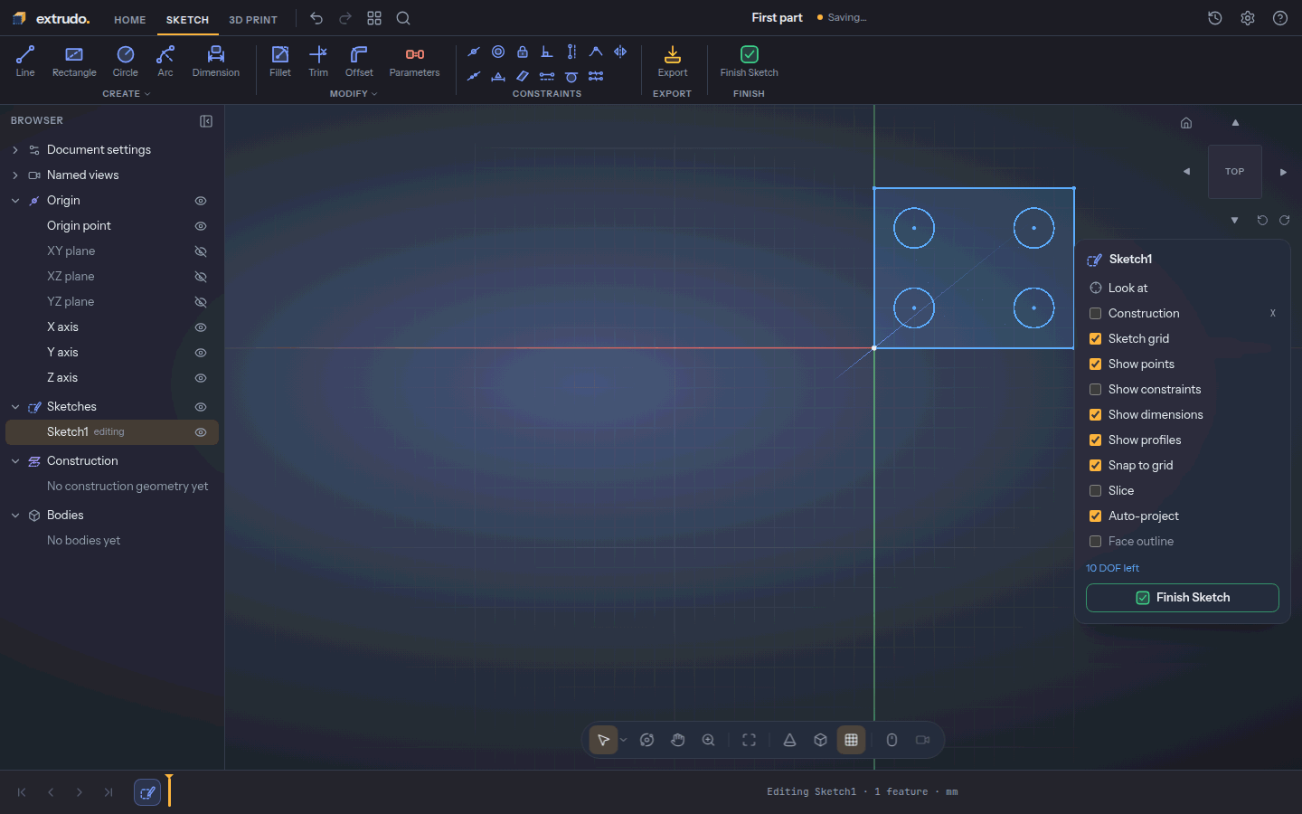
Press Circle (or C). For each hole, click its centre, then click 10 mm to
the side to set the radius. The centres are at (20, 20), (80, 20), (20, 60) and
(80, 60) mm. Press Esc when all four are in.
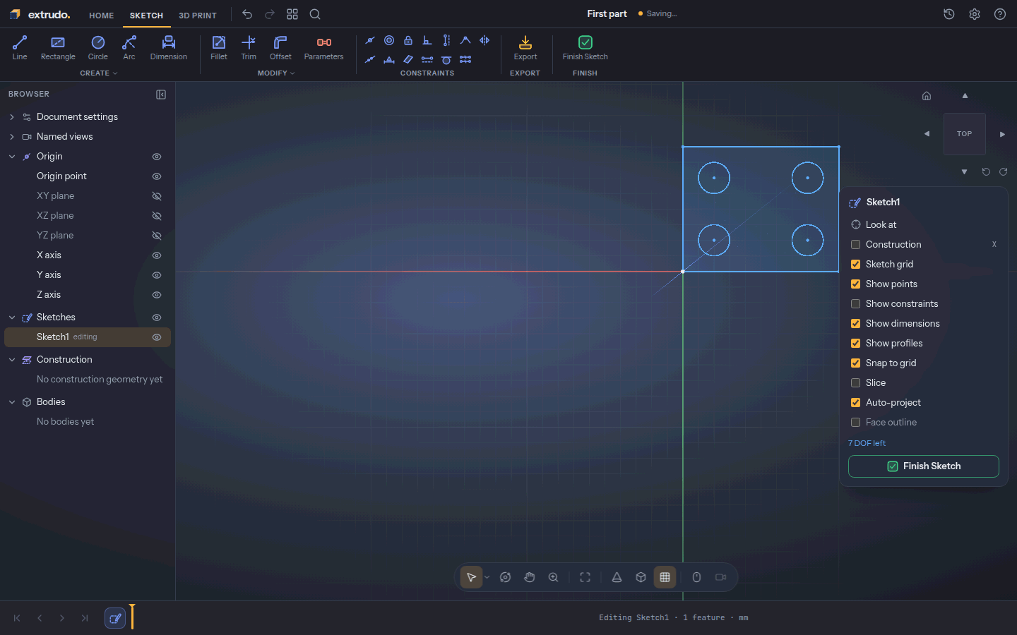
Extrudo noticed that the centres line up in rows and columns and added those constraints for you. The palette now counts 10 DOF left.
5. Make the holes the same size
In the Constraints group press Equal. Click the first circle, then
another circle; repeat for the other two. A constraint is a rule the drawing
keeps, here "these circles have the same radius". The palette says
7 DOF left. Press Esc to leave the tool.
6. Dimension the plate with your parameters
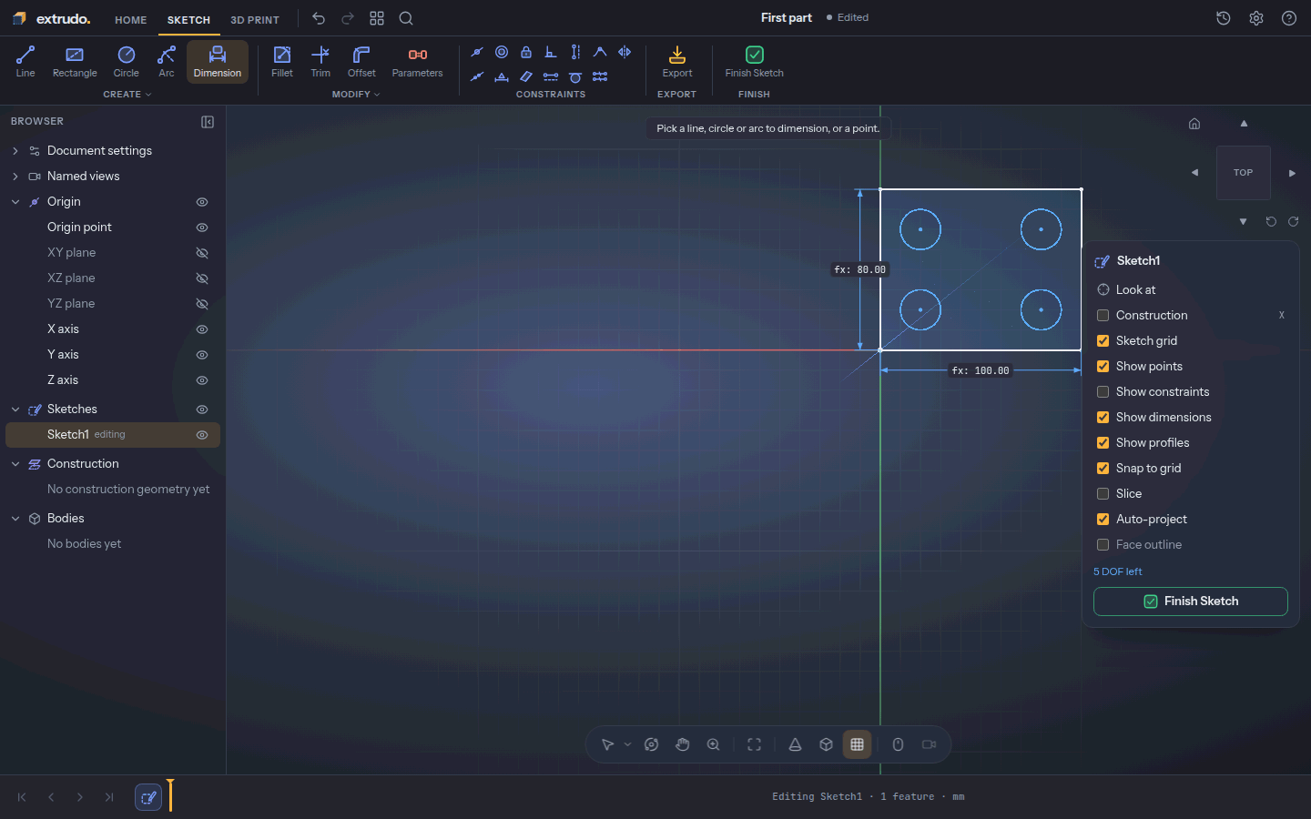
Press Dimension (or D). Click the plate's bottom edge, then click below it
to place the label. An editor opens: type width and press Enter. Now click
the left edge, click to its left, type depth and press Enter.
You did not type 100 or 80. The label shows the parameter's value, so the sketch will follow it when it changes.
7. Dimension the holes
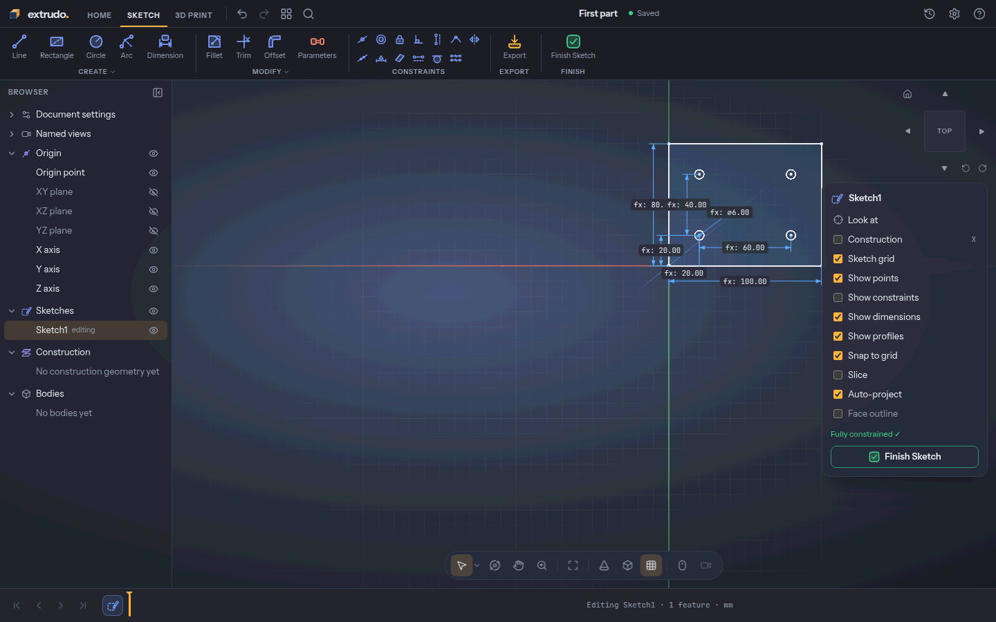
Keep the Dimension tool going and add five more, the same way (pick, place the
label, type, Enter):
- The two bottom hole centres, label below:
spacing. - The two left hole centres, label to the left:
depth - 2 * margin. This centres the holes top to bottom. - The origin and the bottom-left centre, label below:
margin. - The same two points, label to the left:
margin. - The bottom-left circle's edge, label outside:
hole.
Press Esc. The palette reads Fully constrained ✓: every part of the drawing
is pinned by a number, so nothing is left to chance.
8. Finish the sketch
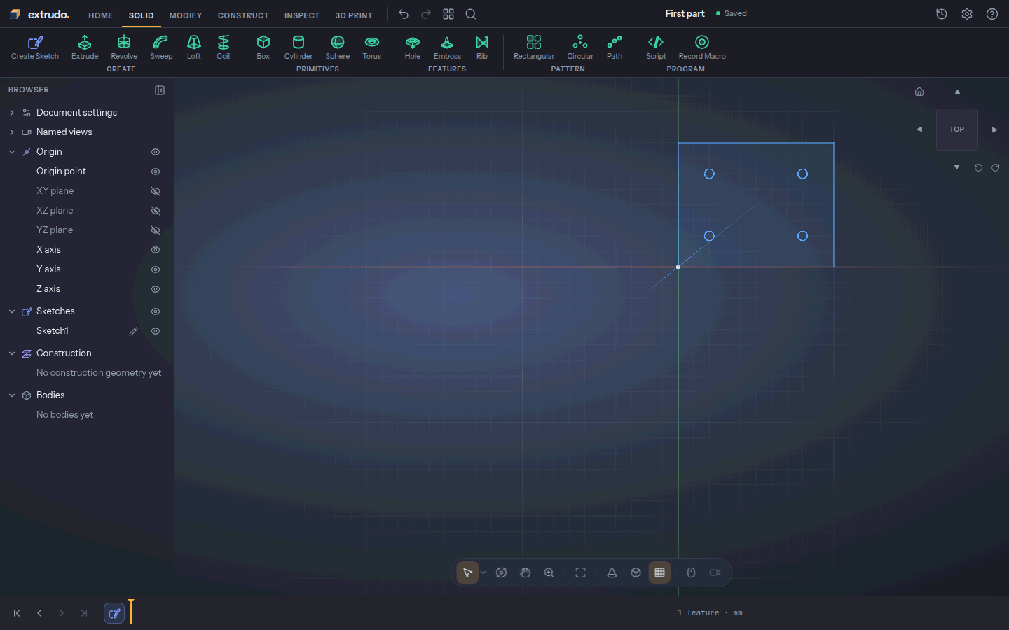
Press Finish Sketch. Your sketch appears in the timeline at the bottom as
Sketch1. The timeline is the list of steps that made your part, in order.
9. Give the plate thickness
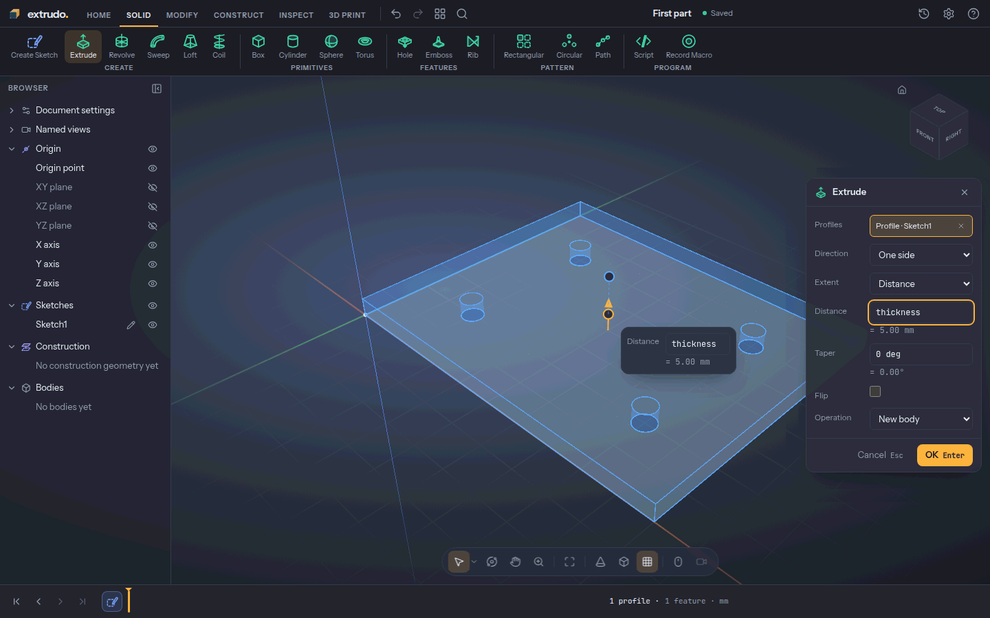
Click the plate between the holes to select its shape, and press E (Extrude).
Type thickness in Distance. The preview shows a plate with four holes
through it. The default Operation is New body, which is what you want.
10. Press OK
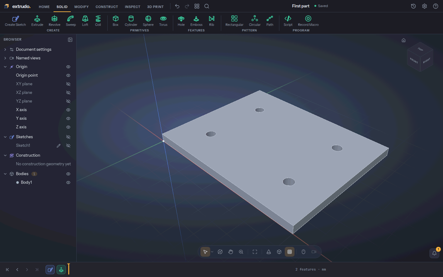
Press OK. You now have a solid, Body1, and Extrude1 joins the timeline.
It is 100 × 80 × 5 mm with 10 faces: top, bottom, four sides and four hole walls.
11. Change a number and watch the part follow
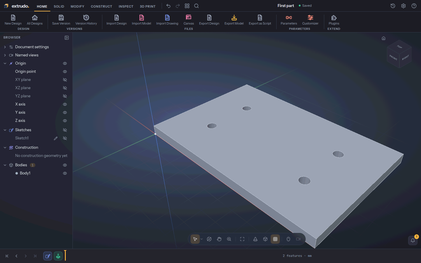
Open the Home tab, press Parameters again and change width to
120 mm, spacing to 70 mm and thickness to 6 mm. Press Esc.
The plate is now 120 mm wide and 6 mm thick, and the holes have moved with it,
because the sketch and the extrude follow their parameters. If you do not like
it, Ctrl+Z undoes the change.
12. Export for printing
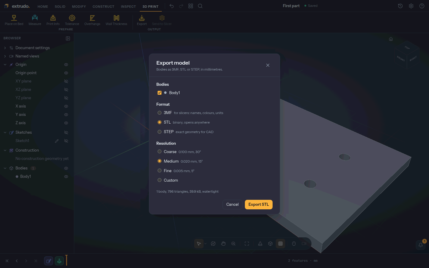
Open the 3D Print tab and press Export. Choose STL. The summary says the model is watertight, which means a slicer can read it without repair. Press Export STL and the file downloads.
What you learned
- Named parameters drive dimensions and features, so changing one number changes the part.
- A sketch is a drawing kept in shape by constraints and dimensions; Fully constrained means nothing is left to chance.
- Extrude turns a sketch shape into a solid, and the timeline records every step so you can come back and edit.
- Export writes a file your slicer can print.
Related tools: Rectangle, Circle, Equal, Dimension, Parameters and Extrude.